Model Validation
Quasi-Static Punch Shear Test (QS-PST)
Problem Description
The calibration of material properties is carried out by simulating the test circular plates (22 layers of woven S2-glass/SC-15 epoxy) using solid elements (single point integration) in LS-DYNA. The blunt steel punch (12.7 mm diameter and 50.8 mm height) is modeled as elastic material whereas the solid supports at top and bottom with circular cutouts are modeled using rigid elements. The plates are modeled with 22 layers of elements in the thickness direction and a fine mesh around the punch. A surface-to-surface contact has been defined between the upper (lower) supports and the plate. Eroding single surface contact has been defined between the steel punch and the composite plate. Fig. 1 shows the meshed models for plates with 25.4 mm and 101.6 mm diameter support span using quarter-plane symmetry. For models using MAT 162, interface element layers are defined by providing different orientation angles at specified interface layers. The material properties used in this simulation are presented in Table 1. Boundary conditions are set up with surface-to-surface contact between the upper and lower supports to the plate with ends unrestrained. Details can be found in Xiao et al., 2005.
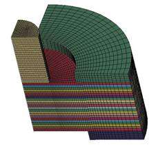
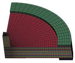
Fig. 1. Quarter-plate model for 25.4mm and 101.6mm span punch-shear tests
TABLE 1 : Material Properties and calibrated parameters for PW (5×5) S-2 Glass/SC15 Composite Laminates
|
MID |
RO, kg/m^3 |
EA, GPa |
EB, GPa |
EC, GPa |
PRBA |
PRCA |
PRCB |
|
1 |
1.85E+03 |
27.5 |
27.5 |
11.8 |
0.11 |
0.18 |
0.18 |
|
GAB, Gpa |
GBC, Gpa |
GCA, Gpa |
AOPT |
||||
|
2.9 |
2.14 |
2.14 |
2 |
||||
|
XP |
YP |
ZP |
A1 |
A2 |
A3 |
||
|
0 |
0 |
0 |
1 |
0 |
0 |
||
|
V1 |
V2 |
V3 |
D1 |
D2 |
D3 |
beta |
|
|
0 |
0 |
0 |
0 |
1 |
0 |
0 |
|
|
SAT, MPa |
SAC, MPa |
SBT, MPa |
SBC, MPa |
SCT, MPa |
SFC, MPa |
SFS, MPa |
SAB, MPa |
|
604 |
291 |
604 |
291 |
58 |
850 |
300 |
75 |
|
SBC, MPa |
SCA, MPa |
SFFC |
AMODEL |
PHIC |
E_LIMT |
S_DELM |
|
|
58 |
58 |
0.3 |
2 |
10 |
0.2 |
1.2 |
|
|
OMGMAX |
ECRSH |
EEXPN |
CERATE1 |
AM1 |
|||
|
0.999 |
0.001 |
4 |
0 |
2 |
|||
|
AM2 |
AM3 |
AM4 |
CERATE2 |
CERATE3 |
CERATE4 |
||
|
2 |
0.5 |
0.2 |
0 |
0 |
0 |
Results
(a) 25.4mm span |
(b)101.6mm span |
Fig. 2. Simulated force-displacements of 25.4mm and 101.6mm span punch-shear tests
(a) Experiment (b) Prediction
Fig. 3. Fiber tensile/shear failure at different punch displacements for 25.4 mm span
(a) Experiment: A – 0.7 mm, B – 1.27, C – 3.39, D – 5.71, E – 22.86
(b) Simulation: A – 0.6 mm, B- 1.20, C – 4.80, D – 9.00, E – 14.00
(a) Experiment (b) Prediction
Fig. 4. Fiber tensile/shear failure at different punch displacements for 101.6 mm span
(a) Experiment: F – 1.52 mm, G – 2.54, H – 8.89, I – 11.86, K – 25.4
(b) Simulation: F – 1.50 mm, G – 2.70, H – 9.00, I – 12.00, K – 16.2